
Project 2a: Building Modeling
12:57 AM
Task:
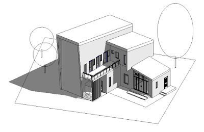
- To generate a Revit model based on a selected architectural design. The model must be compliant
with LOD200 requirements.
- To include at least two Revit Family components.
- Work in Progress (WIP) print screens and test renderings to be uploaded to online platform
regularly to show progressive evidence of the working process. It will serve as a communication
and mutual learning platform.
Work in Progress:
1. Set up building grid lines in floor plans, both vertical and horizontal. With annotated dimensions for reference.
In Datum tab > Go to Grid > Start drawing the grid lines

2. Set up grid lines on 4 elevations views, similar to floor plans.

3. Sketch walls on floor plans, including ground floor, level 1, and basement.
>In Architecture tab > Build >Select Wall:Architectural
>Select appropriate construction layers and materials with the right thickness.


4. Sketch floor slabs on floor plans, including ground floor, level 1, and basement.
>In Architecture tab > Build > Select Floor:Architectural
>Select appropriate construction layers and materials with the right thickness.


6. Followed by second floor form.

7. Same goes to the basement level.

8. Sketch roof using "Roof by Footprint" tool.
>In Architecture tab > Build >Select Roof by Footprint > Sketch

9. Walls are attached to the drawn roofs using "Attach Top/Base".
> Select walls > Go to Modify tab > Attach Top/Base > Select roof

10. Roofs are formed.
>Select appropriate construction layers and materials with the right thickness.


11. Create stairs.
Go to Architecture > Circulation > Stairs > "Stair by Sketch" or "Stair by Component"
> Sketch a line to indicate the desired stair path > Adjust tread and riser dimension in "Properties".


12. Create railing.
Go to Architecture > Circulation > "Railing" > "Sketch Path"
> Then sketch the desired path for the railing.
*offset of 100mm is applied, with the use of "pickline" tool.
*thread and riser dimention is adjusted in Properties.


13. For individual staircase, Opening Cut should be done on the floor slab.
Architecture > Opening > By face > Select floor > Sketch the boundary of the opening
For multiple staircase with the same location on each floors, Openings is done together.
Architecture > Opening > Shaft > Select floor > Sketch the boundary of the opening


14. Due to the different position of stairs in different levels, I have to create the stairs separately, by
the help of "Copy" and "Paste:Alligned to Selected Level" tools.

14. Locate doors.
Option 1: Go to Architecture > Build > Select the default doors in Revit
Option 2: Go to Insert > Load Family > Select the existing / downloaded families of doors


Option 3: Create a custom Door Family for specific use
*doors can be put either on plan or 3D view, In Properties, Constraints can be adjusted, such as
Level and Sill Height.

14. Locate windows.
>Steps refer to Doors.

CREATE FAMILY
15. For Option 3, to create a custom family for door and window:
A. Door Family
1. Go to New > Family > Choose Metric Door template

2. A template is shown.
> Sketch References Lines / References Planes needed > Add parameter
> Name and add dimensions > Lock Constraint.

Go to Create > Choose the tools to create the desired door.

3. In my case, Sweep is firstly used to make the door frame.
Create > Sweep > Pick path on elevation

Select the Green tick button > Go to Floor Plan to sketch the shape of the door frame.

Sketch the door frame in Floor Plan

Sweep applied shown in 3D view.

4. Now, Go to Create > Solid Extrusion > Sketch the Door Panel
> Lock constraint on Reference Planes.


5. Create Door Panel. Create > Solid Extrusion > Sketch the Door in Elevation.

6. In plan view, Door panel dimension is adjusted by aligning it to the references line
and then Lock Constraint.

5. Similar to the Door Panel, a Void Extrusion is created. This is the void to locate glass panel.


6. Same steps applied to the glass panel.


7. Materials is applied in the Properties on the glass panel.

8. Save > Load file into Project.

9. The visibility settings need to be adjusted for a proper drawing on the Floor Plan

10. Go back to the Door Family > Select the unnecessary elements
> Go to Visibility Setting (VG command) > Untick Plan/RCP and When cut in Plan?RCP


12. Load it again in the project. However, the model line is showed in 3D.

13. To solve this, Go back to Family > Select the model lines > Convert Lines
so that the model lines are changed to symbolic lines, which will not be shown in 3D view.


14. Load the file again > the symbolic line is not shown in the 3D view anymore,
it is only shown in floor plan.

B. Window Family
Similar steps are applied in creating a Window Family.
1. Choose Metric Window template

2. Select desired dimensions for window height and width.


3. Draw reference planes.


5. Start sketching the window frame using Solid Extrusion.

6. Lock constraint the sketch path to reference planes.

7. Extrusion shown in 3D view. Frame thickness to be adjusted in plan view,
similar to the Door Family.

8. Create Extrusion for the Glass Panels. Lock constraint to reference planes.

9. Apply glass material.


11. Parameter is added when necessary.


13. Again, adjust the visibility settings of the elements.

14. Create model line > Sketch > Select lines > Convert Line > Symbolic lines are made.

15. Load into project again.


16. Based on the building design, wall openings are created on certain parts.
Architecture > Opening > Wall Opening > Select wall > Sketch opening


* Detail Line (DL command) is used to ease the process.


* Copy (CO command) is used to ease the process for multiple identical openings.


17. Timber columns added.
Structure > Column > Timber column > Locate in Plan.

Similar to wall and roof, Columns are attached to Floor Slab using Attach Top/Base tool.


18. Toposurface and Site Component are added.
Go to Massing & Site > Model Site > locate components accordingly


18. After finish the model, apply materials onto each components.
> Select component > Go to Edit Type in Properties > Duplicate and name the component.

> Add and adjust the Layer function, material, thickness and accordingly.

19. Change the Visual Style to Realistic to check the effect of materials application.

0 comments